Behind the Solar Boom, a Quieter ProblemIssuing time:2026-11-02 17:48 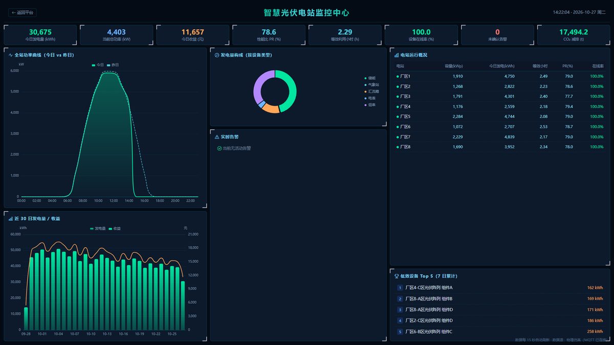 Distributed PV has scaled rapidly, yet the operational layer has not kept pace. A modern plant is, fundamentally, a data-generating asset: behind every array sits an inverter, a combiner, a meter and a weather station, each emitting second-level time-series readings over RS485/Modbus, DL/T645 or IEC protocols — frequently siloed within the inverter vendor's own cloud. As fleets grow from a single rooftop to dozens of sites and hundreds of devices, the challenge shifts decisively from generation to operations: ensuring every string performs, detecting faults before they cost a day of generation, and quantifying plant-level yield and revenue under a unified accounting model. This article examines that operational gap, and the platform architecture designed to close it. The four pain points nobody puts on the brochureDistributed PV is, by definition, distributed. Panels sit on factory roofs in eight different cities, fed by inverters from half a dozen vendors, each with its own app and cloud. The operational reality tends to look like this:
Scale makes all of this worse, not better. A different mental model: the plant as a managed assetWe built the Smart PV Power Station O&M Platform around a simple idea — treat a solar plant the way a factory treats a production line. Not as a pile of hardware, but as a continuously monitored, continuously improved asset. Three capabilities define it: 1. Full-link monitoring. From individual strings to grid connection, device status is surfaced in one dashboard. A plant manager can drop from a fleet view into a single device in two clicks. 2. Closed-loop maintenance. An alarm becomes a work order, the field technician logs handling with photos, and the closure is archived. The loop is traceable end to end — no ticket lost between a phone call and a chat group. 3. Data you can run a business on. Generation, revenue, and carbon reduction are quantified together, with reports that finance can actually export and trust. In our current demonstration environment — which runs in physical simulation across 8 plants, 96 devices and 13.42 MWp — the system shows a 100% device online rate, a performance ratio of 80.48%, and zero active alarms, refreshing every five seconds. The daily generation, revenue and carbon figures update live. (Those numbers come from a simulation, but the pipeline that produces them is the same one a real site would use.) 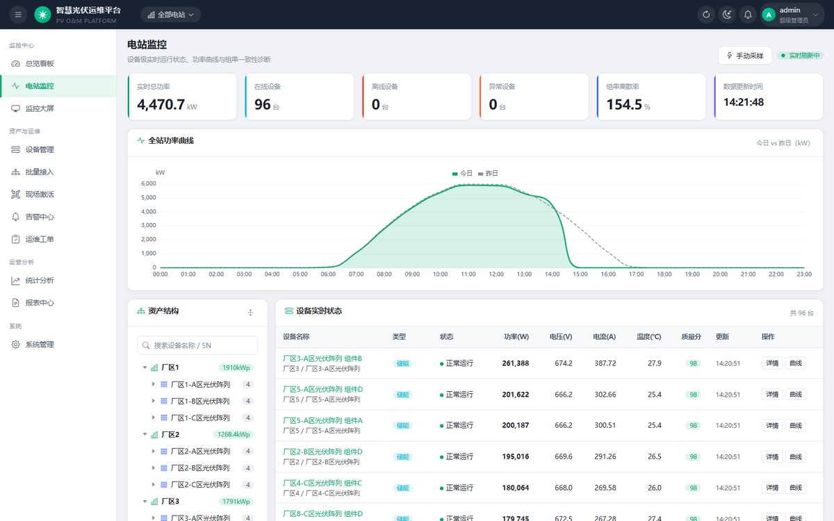 The design choice that matters most: don't touch the original linkHere is the part engineers care about, and the part we are most deliberate about. A solar site almost always already has a data path: the inverter vendor ships its own collection module — Huawei's SmartDongle, Sungrow's Logger, Ginlong's G3-Logger, and so on. The owner paid for it, and it carries their warranty and remote-support relationship. So the worst thing a new O&M platform could do is rip that out.
We chose a third path: bypass collection. A passive listener sits on the RS485 line through a dedicated T-splitter. The original dongle keeps talking to the vendor cloud exactly as before — that link is 100% preserved. Our gateway simply reads alongside it.
To make that safe and reliable, four principles guide the access layer:
The philosophy is simple: respect what is already there, and add value without disturbing it. Under the hoodThe platform is a clean four-layer stack:
Time-series data is tiered — raw → 5-minute → hourly → daily — compressing total storage to roughly 0.7% of the raw volume while keeping second-level traceability for troubleshooting and daily/weekly trends for strategy. Protocol support covers Modbus RTU/TCP, DL/T645 and IEC 103/104, so multi-vendor inverters are read through one uniform layer. Three PV Access Scenarios: C&I Rooftops, Utility-Scale Plants, and Mountain Distributed SitesThe same platform does not mean the same field kit. The access layer is sized to the site's existing network and equipment, not to a one-size-fits-all template. Three scenarios cover the vast majority of distributed portfolios: 1. C&I rooftops — use the LAN that is already there. Factory roofs typically have corporate Ethernet in place, with inverters scattered across floors or buildings and often from a single brand. The recommended kit is a universal data-acquisition gateway plus the grid-connection meter. The RS485 bus is tapped in parallel, then handed to the plant's Ethernet and up to the platform. Because the vendor's original collector keeps its warranty channel intact, one gateway handles both acquisition and forwarding — most sites are onboarded within a single day. 2. Utility-scale plants — partition, then ring. Ground-mount arrays are spaced far apart, split into multiple sub-arrays, and usually tie into a step-up substation. Here the kit scales up: partitioned communication managers, bay-transformer monitoring, and a meteorological station. Each partition's manager feeds the station-control network, which serves both grid-dispatch reporting and the O&M dashboard from one data stream. RS485 runs are segmented at 1000 m and backed by a fiber-optic ring spanning the whole site, so a single copy of the data satisfies both the regulator and the operator. 3. Mountain / broadband-less distributed — go cellular, with local buffer. Remote sites have scattered points, no broadband, and constrained construction and power. The kit drops to a 4G data-acquisition gateway with optional solar power. RS485 goes straight to the all-band 4G uplink to the platform — no dependence on on-site broadband; power on, activate the SIM, and it is online. Sites expand one by one, and local store-and-forward absorbs carrier-signal fluctuations. Optional overlay — site safety. A universal edge-AI video server with ONVIF-compatible IP cameras can be added for perimeter intrusion, fire-smoke detection, and helmet / workwear compliance, with graded alarms forwarded into the platform's work-order flow. One caveat that governs all three: projects connected to grid dispatch must, per local requirements, add separate longitudinal encryption, AGC / AVC coordination, and IEC 104 / 61850 reporting — outside the platform's standard access kit. What "operating solar as a business" really meansThe industry talks a lot about levelized cost and panel efficiency. Those matter. But for the owner of a distributed portfolio, the daily question is more mundane and more important: is everything producing what it should, and do I know the moment it isn't? A platform like this does not generate a single extra kilowatt. What it does is remove the friction between a fault happening and a fault being fixed — and between data existing and a decision being made. Over a year of small, silent losses avoided, that compounds into real yield. The solar boom was won on the generation side. The next chapter — the profitable one — will be won on operations. If you are building or operating distributed or utility-scale PV and want to see the platform in a live demo, reach out at marketing@alinket.com. The solution brief covers architecture, the bypass-access method, and per-scenario sizing in detail. |
Related Products
Go from this article to the product pages — specifications, interfaces and integration details.
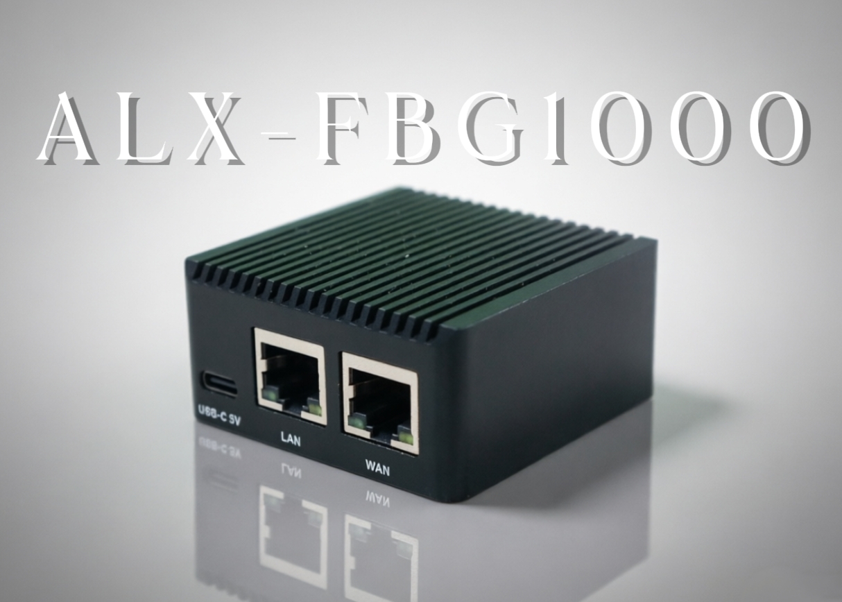
ALX-FBG1000 Data Stream Border Gateway
The ALX - FBG1000 Data Stream Border Gateway is a high - performance data gateway launched by Zilian Electronics Technology, specifi…
View product →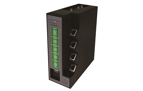
ALXE10B Industrial Edge Computing Gateway
ALXE10B is an industrial edge computing gateway with multi-interface support and protocol conversion.
View product →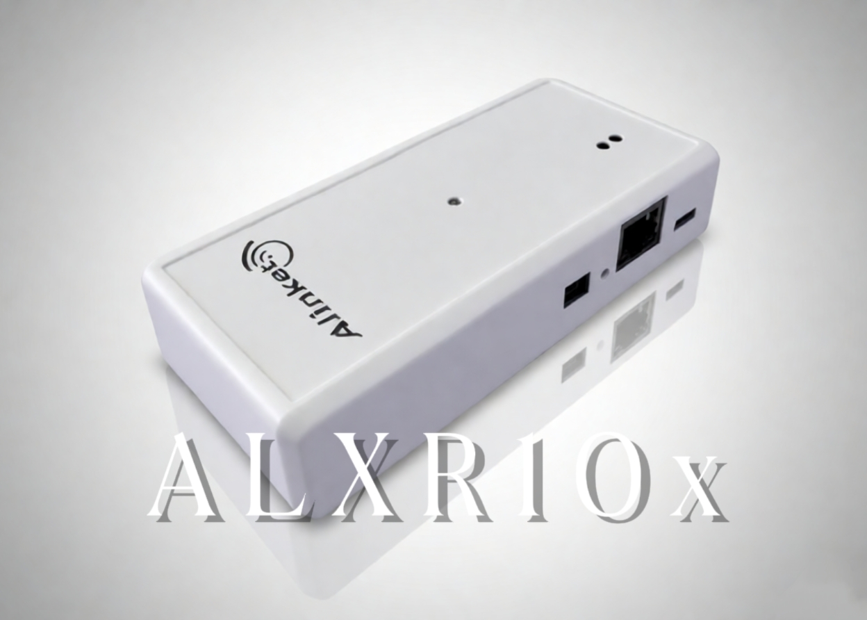
ALXR10 4G LTE Industrial Router
Explore the ALXR10 4G LTE Industrial Router, which seamlessly converts Ethernet/Wi - Fi AP to 4G cellular.
View product →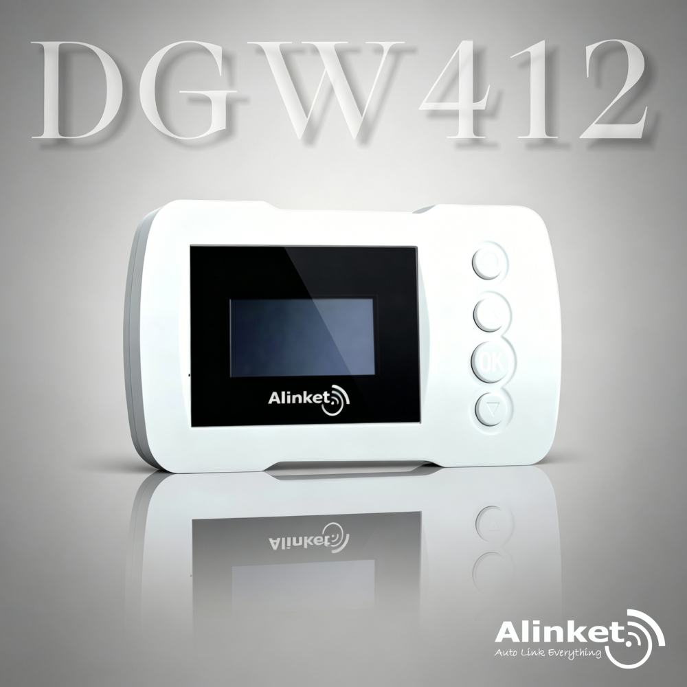
DGW412 BLE to 4G CAT1 Gateway
DGW412 supports BLE 5.0 multi-device connectivity with 4G CAT1 wide-area transmission, connecting up to 6 BLE devices.
View product →Let us build the most stable and fastest network for you
Deeply rooted in the IoT industry for 13 years, we tailor a new smart interconnection experience covering all scenarios for you.
Tell us what you are building — volume, timeline and target market — and the team will come back with the right module, SDK and reference design.